Bridgeport BOSS CNC Control Retrofit Part 1 (Intro)

I picked up an old Bridgeport BOSS CNC mill a while back.  It has spent the last few years languishing in the corner of my buddy Jon’s shop.  Prior to that it was supposedly prototyping parts destined for Harley Davidson.  After an offhand inquiry one day, it was offered up for sale.  A bit of research convinced me that I was just enough of a glutton for punishment to add it to my project list.

Y axis Bridgeport ways
Dusty… but nice ways

The bones of the machine are actually in pretty nice shape.  The table is devoid of idiot marks.  The ways still have their chrome, and the ballscrews all look really nice.  The spindle runs smooth & quiet all the way up to it’s 4500 RPM maximum.  It’s apparent that this machine was well cared for.

The control and power cabinets are excessively large by today’s standards, but nicely constructed.  A close examination serves as a testament to the care and competence once embodied by America’s workforce.  Wires are all well labeled and neatly run.  Airflow within the cabinets is well thought out.  The build quality is representative of a time when companies weren’t so pressed to squeeze every stray penny of cost savings out of a product, and could build to a higher standard.  I couldn’t help but get a bit nostalgic when looking these over.  It’s going to be a little sad to gut them, but times change and a new control system will ultimately save this machine from the scrap heap for another couple decades or more.

Blueprint of BOSS schematic
Schematic

The original hand drawn schematics in true “blueprint” form are still with the machine and are super cool.  The neatness of the drawings puts my chicken scratch to shame.  The drawings are all still readable despite a bit of mouse chewing here and there.

CNC Control:

No doubt it was state of the art when it was new in 1977, but it’s in serious need of updating now.  There are lot’s of options out there in the DIY CNC realm and it took a fair bit of research to decide which direction I wanted to go with it.  For a few hundred bucks, one can install some Gecko drives and retain the original steppers.  This setup can be controlled with an old PC and a Mach3 installation.  Near the high end of the price range are the Centroid retrofit kits at somewhere north of $11,000.

Operator panel – with single line display

The goal for this project is not only to put an old machine back into useful service, but to improve it’s capabilities in the process.  The factory stepper motors on this machine are only capable of 0.001″ resolution, so the stepper motors are going away and the low budget option along with them.  The Centroid kits look pretty nice but the cost puts me within spitting distance of just purchasing a good used CNC with the same or better capabilities.  Besides, if I did a bolt on kit there wouldn’t be much to learn or to write about.  This mill makes for a convenient platform to get me started building CNC controllers, which happens to be another goal of doing this retrofit.

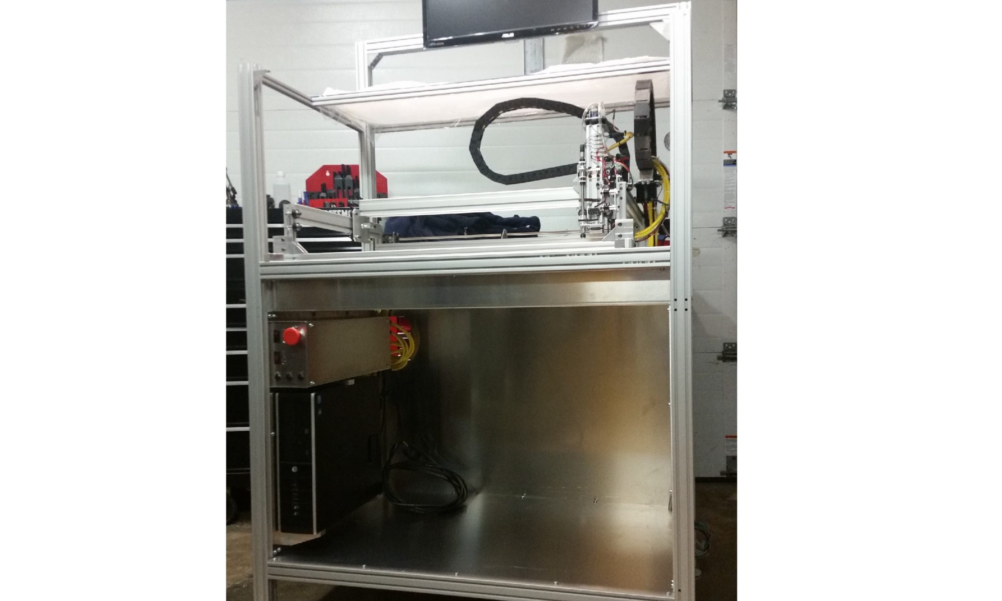
It was decided that the right solution was to roll my own using various commercially available components.  The axis motors will be replaced with servos.  A new CNC controller will be assembled to suit the application.  The enormous cabinets will get removed along with all unnecessary components, and the machine will get completely re-wired.

This isn’t going to be a high priority project for me, so updates will come along on a “whenever I get to it” sort of schedule.  I do plan on covering the various aspects in detail though.  So keep checking back and you’ll occasionally find a new write up.


Liteplacer Build Part 3

Partially built pick & Place machine

The third installment in this series covers the construction of the frame/enclosure and the wiring of the machine.  Check out part 1 and part 2 of the build if you haven’t already.

Frame Rendering

I decided to build a dedicated frame & enclosure for my Liteplacer rather than mount the machine to a table like it was designed.  Since the plan is to add feeders and other features over time as needs evolve, the added cost of 80/20 extrusion seems justified.  I had previously designed the frame in Solidworks and the extrusions were ordered cut to length.  All that was left to do was drill a few holes, tap some of the ends and assemble.


Hole drilling with Bridgeport mill
Drilling Holes

Speaking of tapping… why is it that you never seem to break a tap when you have a spare?  But always seem to when you don’t.  Murphy’s law of course came into play… and I ended up donating my only 5mm tap to the scrap bin.

Liteplacer Enclosure Frame With Controls
Assembled Frame With Controls Mounted

Putting this all together necessitated the manufacture of several parts.  A total of 12 custom brackets were manually machined on the ole Bridgeport.  Mounts for the footpads, monitor, PC, and the brackets to mount the Liteplacer into the enclosure were created.  There is something uniquely satisfying about using machinery to build more machines, but all the handle turning really had me wishing for a CNC… more on that in a future post.

The Liteplacer mounts into the frame with a machined bracket at each corner.  I also made up a center bearing support out of some 0.125″ aluminum.  This supports the Y axis shaft center bearing from the frame, and allows removal of the Liteplacer’s rear crossbar.

Cables connected to control enclosure
CNC Control connections

With the machine mounted, it was time to wire it up.  Continuous flex rated cable was used for all the moving runs of wire.  I found some Trex-Onics 18AWG / 6 conductor shielded cable on ebay that was reasonably priced.  The axis motors and limit switches were all wired in using this shielded cable.  The cables were terminated at the control end using Amphenol C 091 A Series connectors to mate up to the control box.

Relocation bracket for Y axis cable guide
Cable guide bracket

The Y axis cable carrier ran a little long for my enclosure and was going to hit the front cover when the Y axis came all the way forward.  I cut a piece of 0.125″ aluminum and formed up a relocation bracket to move the mounting point rearward which afforded me plenty of room.

While the 80/20 extrusion is really nice for it’s adaptability, it doesn’t make for a particularly rigid frame without cross bracing it.  You’ll notice in the picture and rendering at the top of this post that I’ve added some aluminum panels to the bottom, rear and sides of the machine.  In addition to better enclosing the machine, these serve as structural elements, effectively cross bracing the machine in all three directions.  The polycarbonate covers on the upper portion of the machine will also add a bit of rigidity, albeit to a lesser extent than the aluminum panels.

The plates are 0.125″ 5052 aluminum, and the pan that sits just under the open bed area is 0.080″.  These parts were laser cut at a local shop that also did the forming of the “bed pan”.  The polycarbonate covers are 3/16″ thick, and used up an entire 4′ X 8′ sheet.  I laid these out in Solidworks and pestered my buddy Jon until he cut them on his router table.

Most of the polycarbonate covers won’t be installed until the rest of the details are sorted out and the machine is up and running.  I’ve got at least one or two more posts worth of details to cover before the machine is finished.  I still need to build and mount the vacuum reservoir.  I also need to build circuit board and parts holders.  Then it will be time to load software and start placing components.  Thanks for reading and keep an eye out for updates.

Custom Puller Tools

Here is a pair of custom puller tools that I recently designed and built for a customer.  These are used to remove impellers from large centrifugal irrigation pumps.

I designed these to use commonly available hardware for all the wear parts.  The central nut is a grade 8 coupling nut, and the jacking screw is 5/8-18 grade 8 threaded rod.  The central nut is captured in a machined pocket between the side plates and rests against a thrust plate that spans the side plates and locks into a slot in either side.


The top plates saddle over the side plates to prevent the sides from spreading under a heavy load.  The customer will be using two different threaded rods on the sides to attach to the pumps (1/2″-13 & 3/8″-16.)  So I drilled the center hole at 1/2″ and made the counterbore to fit the 3/8″-16 flange nut so the plate will hold either size centered.


This project turned out to be a little more time consuming than I originally predicted.  I am however happy with the results – simple, and effective, with commonly available wear parts.

Label Slicer Tool

This is my first post in what I expect will become a series detailing some useful small scale manufacturing techniques.  Anyone who attempts to bring niche products to market will find that there are unique challenges in producing small product volumes.  Many times the low volume makes outsourcing much of the assembly and production work cost prohibitive while the time requirements of using low cost manual techniques in the modest home shop can quickly get out of hand when faced with fulfilling orders of 10, 20, or 50 of your product.  If you are working a full time job and building widgets on the side, the prospect of coming home from a full workday and facing another 6 to 10 hours of work before bedtime gets old FAST!

So… what is the inventor and entrepreneur to do?  The answer is to get smart (efficient) with our manufacturing techniques and our time.  In these posts I will show what that age old adage of “work smarter not harder” looks like when the rubber meets the road and it’s put in to practice.  Ok, enough with the preamble and on to the meat of the post.

This turned out to be a handy & simple little tool.  I made this a while back, when I was faced with the challenge of trimming down a bunch of labels (about 100) and applying them to these screw terminals.  After doing a couple with scissors and being less than satisfied with the results I decided a better way was needed.  I messed around with some different widths of tape in the label maker, but anything that was narrow enough to fit the terminals resulted in text that was so small as to be nearly unreadable.

So… I ended up printing two rows of labels on a 3/4″ label tape and building this nifty little custom slicer tool to cut them to a uniform and repeatable width.

This little bugger uses standard utility knife blades, so when they get dull its a just a matter of loosening the machine screws and replacing them.

I think the pictures pretty much explain things here.  The blades sandwich in between the machined parts that provide the proper spacing and the whole works is held together with two machine screws.  The “guide block” has a groove machined into it to hold the label and the nose of the cutter is machined to run inside this grove to guide it down the label.

The pictures show the labels being cut face up, this however resulted in some light marring on the face.  I ended up cutting the labels face down so the cutter runs across the backside and the face remains clean & professional looking.  If you don’t have access to machining equipment, I think this idea would work equally well if done with a 3D printer.